 Zhejiang Rsafele Electric Co., Ltd.
Tailoring Transformers for the Demands of Solar Energy
In the global transition to sustainable energy, solar power is becoming increasingly prevalent in utility-scale, commercial, and residential scenarios, propelled by falling costs and technological breakthroughs. At the very core of these solar systems is the solar power transformer-an essential yet frequently overlooked component that is vital to the efficiency and security of any solar setup, whether it's for maintaining optimal voltage levels or enabling seamless integration with the electrical grid.
Solar generation hinges on the sun, a discontinuous power source. The cycles of day and night, along with environmental factors such as precipitation and cloud cover, make its power production cyclical rather than continuous, which directly dictates the demands on transformers in solar applications. This implies that a solar transformer never operates at 100% load around the clock; depending on the season, it might only run at full load for 6 hours each day. This situation gives rise to questions like: "Can we downsize the transformer since it's only loaded part-time?" or "Can we overload it during the day to make up for underloading at night?" The concise answer to both is no-in fact, these situations may even amplify the strain on the transformer.
SCOTECH, a company dedicated to providing innovative and sustainable solar solutions across the globe, with the mission of harnessing solar energy to create a cleaner, greener future for all. From rooftop photovoltaics to solar parks, from industrial applications to agricultural facilities, solar transformers are at the heart of energy distribution. In the ever-expanding solar landscape, while solar panels and inverters often take center stage, transformers ensure that the generated power is efficiently stepped up or down, synchronized, and transmitted safely across grids and infrastructures, thus revolutionizing solar energy systems for commercial and industrial (C&I) uses.
From a wider viewpoint, in the face of the rising global energy demand, the need for friendly and reliable natural energy sources is one of the most pressing challenges of our era. Along with wind and water, sunlight-clean, CO₂-free, and virtually limitless-is among our most valuable resources. To make renewable energy the dominant energy source worldwide, we strive to make it as affordable as conventional energy. By integrating innovations in renewable power generation with smart grid and high-voltage transmission technology - where solar transformers play a crucial role, we can save more energy and costs, laying the groundwork for a sustainable energy future.
The Operational Logic of Transformer-Based Solar Systems
1. Light Energy Capture & DC Generation
PV panels absorb sunlight photons via semiconductor materials, triggering directional electron movement to produce DC power. Key influencing factors: panel area and sunlight intensity.
2. DC-to-AC Conversion
Inverters convert DC power to AC while calibrating voltage, meeting requirements for household use and grid connection (AC-compatible devices/grids).
3. Voltage Regulation
- Step-up transformer: Boosts inverter output (208–690V) to medium/high voltage (11–33kV) to reduce long-distance transmission energy loss.
- Step-down transformer: Lowers high voltage to end-use levels (220V for households, 380V for commercial use) ensuring safety and compatibility.
4. Grid Synergy & Safety Protection
AC power undergoes voltage/frequency (50Hz, China grid standard) synchronization for seamless grid integration. Surge arresters, relays, and circuit breakers prevent faults from lightning, fluctuations, or equipment malfunctions.
5. Monitoring & Maintenance
Dedicated systems track real-time data (power generation, panel temperature, transformer load) and trigger alerts for faults. Routine maintenance (panel cleaning, transformer insulation checks) sustains efficient long-term operation.
What is a solar transformer?
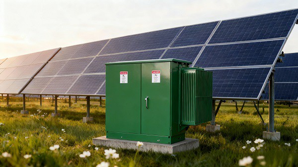
A solar transformer is a customized electrical device specifically engineered for photovoltaic (PV) power systems. Its primary function is to adjust voltage levels generated by solar panels, ensuring compatibility with either the electrical grid or end loads-an especially critical role in large-scale solar projects that require long-distance power transmission or grid synchronization. Designed to accommodate the intermittent nature of solar electricity and tolerate varying loads and climatic conditions, it serves as a linchpin in solar energy production and distribution.
In operation, solar transformers differ from their counterparts in non-renewable energy systems. Historically, transformers "stepped up" or "stepped down" energy from sources like coal or gas, but solar transformers are optimized for the cyclical nature of sunlight. During inverter operation, they experience steady-state loading, with a dampened reaction process when solar generation is active. Notably, solar inverters contribute very low harmonic content (typically below 1%), so harmonics have almost no impact on the system. This is because solar systems lack generators and complex switching/protective controls found in technologies like wind turbines. Moreover, solar transformers operate at relatively stable voltages-rated voltage is controlled by inverters, so voltage and load fluctuations are considerably lower than in wind turbine systems. They also tend to run close to their rated loads. While fault ride-through standards for photovoltaic systems are still evolving (partly due to the technology's youth and the ease of quickly switching solar systems on or off), solar transformers are built to withstand these operational nuances. From rooftop PV setups to vast solar parks, these transformers ensure that energy is efficiently stepped up/down, synchronized, and transmitted safely across grids and infrastructures. Their specialized design-balancing durability, adaptability to low-voltage inputs, and resilience to high-order harmonics or DC components-makes them indispensable to the global transition toward sustainable solar energy.
Types of transformers Used in Solar Applications
In solar applications, a variety of specialized transformers play distinct roles in ensuring efficient energy conversion, reliable distribution, and seamless grid integration. Here's an integrated overview of these transformer types:
1. Inverter-Centric Transformers (Inverter Duty & Inverter Transformers)
Designed to work in tandem with solar inverters, these transformers are pivotal in bridging the gap between solar generation and grid requirements. Inverter Duty Transformers provide electrical isolation between the DC and AC sides, manage voltage transformation, mitigate harmonic distortions to maintain power quality, and enable voltage step-up for grid integration-addressing the unique electrical traits of solar inverters. Inverter Transformers (used in solar parks) step up the AC voltage output (208–690 V) from inverters (rated 500–2000 kVA) to medium voltages (11–33 kV) for collector transformers. They handle voltage polarity reversals, pulsations, and heavy harmonics from inverters, often featuring a grounded electrostatic shield between LV and HV windings to filter harmonics, with mineral oil or ester as insulating liquid.
Applications: Compatible with all major PV system architectures, including both centralized grid-scale deployments and decentralized on-site energy setups.
2. Step-Up and Step-Down Transformers
Step-up Transformers: Increase inverter output voltage to match grid or transmission voltage levels, reducing transmission losses and enabling long-distance power delivery (e.g., solar farms exporting power to the utility grid at high voltage).
Step-down Transformers: Lower voltage for safe, efficient distribution within facilities or off-grid setups, powering lighting, machinery, and HVAC systems.
3. Pad-Mounted Transformers
Ground-mounted and enclosed in secure cabinets, these transformers are ideal for urban/commercial underground power distribution. They handle medium-voltage levels, integrating solar power into local distribution networks with a tamper-proof design.
4. Isolation Transformers
Critical in sensitive/industrial environments, they provide galvanic isolation (without voltage change) to enhance safety, reduce electrical noise, prevent current leakage between panels and inverters, and comply with grid codes-essential where direct electrical connections are avoided.
5. Grid-Tie Transformers
Engineered for connecting solar systems to the utility grid, they enable bidirectional current flow (exporting solar power or importing grid power) and ensure voltage synchronization/grid code compliance, making them a cornerstone of grid-tied solar projects.
6. Zig-Zag Autotransformers
Used for grounding in ungrounded MV circuits, they establish a neutral point via a unique winding configuration. They address unbalanced loads, mitigate harmonics, and improve system stability by providing a path for zero-sequence currents, often deployed in utility grounding banks.
7. Collector Transformers
Collector Transformers aggregate power from multiple inverter transformers, stepping up medium voltage (MV, 11–33 kV) to high voltage (HV, 66–400 kV) for grid transmission. Their capacity is often limited by MV circuit breaker ratings (e.g., ~160 MVA for 36 kV), though transformer designs can reach higher capacities (e.g., 315 MVA). Large units often split the LV side into two separate circuits to limit fault current. They are equipped with On-Load Tap Changers (OLTC), typically installed on the HV neutral, providing ±10% voltage regulation. These transformers are essential for efficient power transmission in utility-scale solar farms.
8. Auxiliary Transformers
Low-kVA three-phase transformers that power inverters and meet station loads. They can be standalone or integrated into inverter enclosures, with primary connections to the grid or inverter's pulsed output. Applications: Cater to the operational demands of utility-scale solar energy facilities.
9. Earthing (Grounding) Transformers
Required in ungrounded MV circuits to create a grounding neutral, they are often zig-zag connected (short-time rated for 10 seconds) with neutral grounded solidly or via a resistor. Star/delta connected transformers can also serve this purpose.
Applications: Serve the operational requirements of utility-scale solar energy installations.
10. Voltage Regulators
Booster transformers with OLTC, installed on inverter transformers' LV/HV sides to manage grid voltage fluctuations. These small auto-transformers use buck-boost OLTC to regulate output voltage by ±10% in 16/32 steps, with ratings up to 250 kVA (LV) or 8 MVA (MV).
Each transformer type is tailored to the unique demands of solar energy generation, distribution, and grid interaction, collectively ensuring the efficiency, safety, and reliability of solar power systems.
Design characteristics
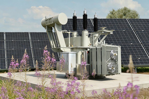
Solar transformer design is tailored to address the unique operational demands of photovoltaic (PV) systems, integrating targeted solutions for inverter interactions, load variability, and environmental exposure. Below are its comprehensive design characteristics:
1. Asymmetric Load and Voltage Performance
Inverter-supplied solar transformers may experience unbalanced three-phase voltages and load currents. When powered by multiple inverters, the inactivity of one unit can exacerbate winding load imbalance. Such unbalanced conditions induce excessive leakage flux, stray losses, and overheating in both windings and the transformer tank.
2. Optimized Winding Configuration
Vertically stacked, loosely coupled low-voltage (LV) windings paired with an equal number of split high-voltage (HV) windings are preferred-this design mitigates the impacts of electrical imbalances. The winding impedance characteristics are defined based on the specific inverter system and the number of inverters connected to the transformer.
3. DC Component Tolerance in Windings
There is a risk of DC current injection into inverter-fed windings. This DC component elevates core magnetizing current and the peak value of inrush current, so designs must accommodate these electrical stresses.
4. Inverter Output Waveform Coordination
When two or more inverters connect to a single transformer, their output waveforms may lack synchronization. This desynchronization causes waveform distortion, harmonic generation, and disturbances to the transformer's core magnetic flux.
5. LV Winding Insulation for Fast-Rising Pulses
Inverters deliver pulsed output to the LV winding, with a voltage rise rate (dv/dt) reaching up to 500 V per microsecond. The LV winding insulation must be engineered to withstand this rapid transient throughout the transformer's service life.
• An electrostatic shield (copper or aluminum; copper minimizes eddy current losses vs. aluminum) is installed between LV and HV windings: it acts as a dv/dt filter to dampen voltage gradients and reduces transient transfer between windings.
• Accelerated aging tests are conducted on prototype LV insulation to evaluate transient impacts; note that dry-type and fluid-filled transformer insulation respond differently to these transients.
6. Loss and Efficiency Optimization
Solar transformers have relatively low no-load losses (they draw exciting power from the grid at night). Efficiency is optimized for specific load cycles to boost operational economy. If the system includes battery storage (enabling continuous loaded operation), efficiency levels can be fixed based on this steady-state condition.
7. Inrush Current Considerations
The LV winding is typically positioned close to the core, resulting in low air-core reactance. Thus, the inrush current when energizing the LV side is relatively high-a factor addressed in protection and design.
8. Targeted Thermal Design
The cooling system is engineered to account for site-specific environmental temperature fluctuations, load profiles, harmonic effects, and reactive load impacts-ensuring effective heat dissipation under variable conditions.
9. Short-Circuit Resilience
Winding configurations and short-circuit locations influence the magnitude/distribution of short-circuit currents. Designs address multiple scenarios: HV-side short circuits, short circuits on one/multiple LV sides, and short circuits between LV windings.
10. High-Frequency Switching Transient Management
The HV side uses vacuum circuit breakers (VCBs); VCB pre-strikes/re-strikes (paired with cable capacitance and transformer inductance) generate fast-rising transients that risk insulation failure.
• Designs reference IEEE Standard C57.142-2010 (a guide to switching transient mitigation).
• Simulations (covering up to 2 MHz, using cable/transformer parameters) calculate VCB-induced overvoltages to optimize insulation.
11. Specialized Installation & Operation Practices
Inverters connect to star-connected LV windings, so the neutral point is kept floating (not earthed/grounded)-isolating the neutral inside the transformer is a safe design practice. Transformers with electrostatic shields require single-point earthing for the shield.
12. Harmonic Distortion & Thermal Resilience
PV inverters introduce harmonic currents (even with filters limiting distortion to <5%, cumulative heating remains significant). Transformers may use K-rated designs to withstand higher harmonic loads without overheating.
13. DC Bias & Core Saturation Protection
Some inverters introduce DC bias to the transformer input, causing core saturation (increasing losses and overheating). Designs mitigate this risk to ensure reliable operation.
14. Overloading & Sizing Strategy
Inverters may output power exceeding their rated capacity (under optimal sunlight). Transformers are sized for the inverter's maximum potential output (not just nominal ratings) to prevent overloading.
15. Winding Configuration & Grounding for Grid Compatibility
For grid-tied systems, a common setup is delta connection (grid/primary side) + wye-grounded connection (inverter/secondary side)-this mitigates phase-to-ground voltage imbalances.
16. High-Efficiency Material Selection
Advanced core materials (e.g., amorphous metals) reduce core losses, while optimized winding configurations minimize copper losses-collectively boosting overall efficiency (critical for maximizing PV energy transfer).
17. Environmental & Operational Durability
Solar transformers face variable conditions (temperature swings, outdoor exposure). Designs use robust insulation and protective enclosures to ensure long-term reliable operation.
Trends in the Development of Transformers for Solar Energy Systems
As solar power scales globally-paired with growing grid complexity (from distributed generation, nonlinear loads, and electric vehicle infrastructure)-transformers tailored for solar applications are evolving to meet smart grid demands, efficiency goals, and operational flexibility. Below is a structured overview of key trends and associated considerations:
⚙️1. Smart, Grid-Responsive Design (Enabled by AI & Solid-State Technology)
The rise of "smart grids" is driving transformers to integrate advanced functionality, supported by artificial intelligence (AI), sensors, and solid-state transformer (SST) architectures:
• Dynamic grid support: Next-generation units will deliver features critical for grid stability, including voltage sag compensation (stabilizing end-user voltage), harmonic isolation/filtering (mitigating nonlinear load distortion), dual AC/DC output (for EV charging and DC loads), outage compensation (drawing from energy storage), and fault isolation (protecting grids from localized issues).
• AI & real-time management: Integrated sensors and AI enable real-time monitoring, predictive maintenance (reducing downtime), and adaptive load management-essential for mitigating solar power's inherent variability.
• Solid-State Transformers (SSTs): These units use power electronics to operate at high frequencies, minimizing size/weight while converting voltage to tailored AC/DC outputs. However, SST adoption depends on broader smart grid deployment (currently slowed by utility investment constraints and legacy infrastructure).
☀️2. High-Efficiency & Sustainable Engineering
Materials science and eco-design are central to reducing losses and environmental impact:
• Low-loss components: Amorphous metal cores cut energy dissipation in traditional transformers; for SSTs, low-loss magnetic materials (and emerging solutions like carbon nanotube windings) are needed for high-frequency (HF) cores (a key R&D gap).
• Sustainable materials: Biodegradable insulating fluids and recyclable parts reduce the carbon footprint, aligning with global sustainability targets.
• Efficiency tradeoffs: While conventional transformers reach >99% efficiency, SSTs currently have lower overall efficiency-making efficiency improvements a top priority for commercialization.
🔌3. Modular, Scalable Solutions for Distributed Solar
Flexibility for decentralized installations is a growing priority:
• Modular designs: These units simplify installation, maintenance, and scaling to match dynamic energy demands-making them ideal for expanding solar access in remote or underserved regions.
• Distributed grid alignment: Their adaptability complements distributed solar infrastructure, where localized load management and variable generation require agile energy distribution.
🔋4. Integrated Energy Storage & Advanced Thermal Management
These trends address solar intermittency and operational durability:
• Energy storage integration: Transformers are engineered to pair seamlessly with batteries, storing excess solar energy for deployment during low-generation periods-boosting grid reliability.
• Thermal resilience: Diverse operating environments (e.g., desert farms) require innovations like phase change materials and geothermal cooling to maintain optimal temperatures. This preserves component lifespan and efficiency, especially critical for high-frequency SSTs (which face unique thermal challenges).
⚡5. High-Voltage Capabilities for Utility-Scale Solar
Large solar farms demand transformers that handle elevated voltages:
• Long-distance transmission: High-voltage units enable efficient power delivery over vast distances (reducing line losses) and integration with national grids.
• Component limitations: For SSTs, commercial access to high-voltage devices (e.g., 11 kV/13.2 kV IGBT/SiC components) is limited; cascade connections are currently used as a workaround.
🧩Key Commercialization Challenges
While these trends define the future, critical barriers remain:
• Slow smart grid deployment (tied to utility investment and legacy infrastructure).
• Limited availability of high-voltage power electronics for SSTs.
• Unresolved needs: Surge/fault protection for high-voltage circuits, and low-loss materials for HF SST cores/windings.
Benefits of Using Transformer Solar Technology
1. Exceptional Energy Conversion Efficiency
Solar transformers optimize voltage conversion and AC/DC power transfer with minimal energy loss, achieving efficiencies of up to 99% (compared to 94% for traditional transformer technologies). This high efficiency maximizes solar power utilization, directly boosting energy output for residential, commercial, and utility-scale solar installations. Advanced designs-such as high-frequency three-port windings-further enhance power density by 10x or more, enabling smaller, more compact systems without compromising performance.
2. Robust Reliability & Grid Stability
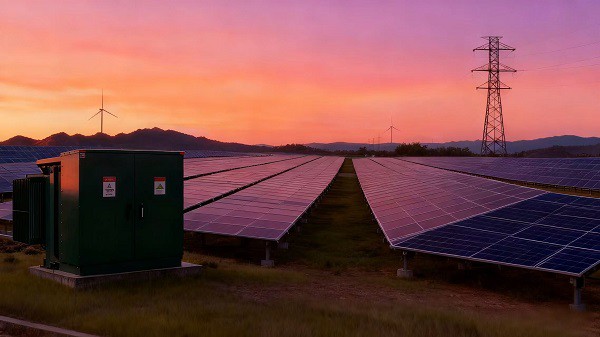
Engineered to withstand the inherent variability of solar irradiance (e.g., voltage fluctuations, harmonic distortion from inverters), solar transformers ensure consistent power flow to the grid. They resist ferromagnetic resonance across a broad capacity range and maintain stable voltage regulation even during peak sunlight or sudden weather-driven power spikes. For utility-scale projects, this reliability reduces curtailment risks and grid compliance penalties, ensuring uninterrupted energy delivery.
3. Superior Environmental Resilience
Built with weather-resistant steel enclosures, corrosion-proof components, and advanced insulation systems, solar transformers perform reliably in harsh operating conditions-including extreme temperatures (-40°C to +40°C), high humidity (up to 100% at 30°C), and dusty/offshore environments. Dry-type solar transformers (e.g., epoxy resin-cast models) eliminate fire risks associated with oil-filled alternatives, while biodegradable FR3 dielectric fluid options enhance fire safety and reduce environmental impact.
4. Lifecycle Cost Savings
Solar transformers deliver significant cost reductions across the project lifecycle:
Installation: Containerized, modular designs cut on-site labor and commissioning time by up to 50%, eliminating the need for specialized lifting equipment.
Maintenance: Oil-free dry-type models require no regular oil testing/ replacement, reducing annual operational expenses by 15–20% for solar plants.
Longevity: With a lifespan of 25+ years (30 years for epoxy-insulated units), they lower the levelized cost of energy (LCOE) by 10–15% compared to conventional transformers, improving project ROI over decades.
5. Enhanced Safety & Compliance
Solar transformers provide galvanic isolation between solar inverters and the grid, mitigating electrical hazard risks. They meet global standards (IEC 61869-3, ANSI/IEEE) for grid compatibility, while flame-retardant materials and explosion-proof designs minimize fire and safety incidents-critical for remote solar installations with limited emergency response access.
6. Flexible Integration with Energy Systems
Designed to integrate seamlessly with solar inverters, battery storage, and microgrid setups, solar transformers support both grid-tied and off-grid applications. Customizable loading profiles, impedance settings, and inverter compatibility make them adaptable to diverse project scales-from residential rooftops to 100MW+ utility solar farms.
Challenges and Solutions in Transformer Solar Projects
Transformer applications in solar power systems encounter several targeted technical bottlenecks; below are the key issues and customized solutions:
1. Harmonic Interference and Temperature Regulation Issues
Challenge: Harmonic currents generated by PV inverters can induce extra heat buildup in transformers, which may compromise their operational lifespan and stability.
Solution: Deploy K-rated transformers (specifically engineered for high harmonic load scenarios) to reduce overheating risks. Pair this with advanced cooling systems and real-time thermal monitoring to dynamically control temperature fluctuations.
2. DC Component Intrusion along with Transformer Core Saturation Risks
Challenge: Some inverter designs may inject DC components into transformer inputs, triggering core saturation-this elevates energy losses and could cause long-term damage to the core structure.
Solution: Utilize optimized core materials and configurations to prevent saturation; conduct regular testing and monitoring to quickly detect and resolve DC bias-related problems.
3. Peak Load Overrun and Rational Capacity Matching
Challenge: Under ideal sunlight conditions, solar inverters may output power beyond their nominal rating, leading to potential transformer overload.
Solution: Size transformers based on the inverter's maximum possible output (rather than just its rated capacity) to ensure they can handle peak load scenarios without overloading.
4. Winding Layout Design as well as Grounding Scheme Optimization
Challenge: Improper winding arrangements can cause phase-to-ground voltage imbalances, creating safety hazards and performance inconsistencies.
Solution: Adopt a delta connection on the grid (primary) side and a grounded wye connection on the inverter (secondary) side to balance voltage levels and enhance operational safety.
5. Ambient Environment Variability and Operational Stability Maintenance
Challenge: Transformers in solar installations are often exposed to fluctuating environmental conditions (e.g., temperature swings, outdoor corrosion), which undermine their performance and durability.
Solution: Equip transformers with robust insulation materials and protective enclosures to withstand ambient changes and external exposure, ensuring consistent long-term operation.
SCOTECH: Core Advantages in Solar Transformer Integration
1. Technical Highlights
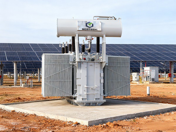
Harmonic Resilient: K-13 design for stable operation under high distortion (3% THD).
High Efficiency: 15% lower losses with adaptive cooling.
Grid Ready: Precise voltage regulation, Dyn11 phase matching, and full protection.
Solar Tough: 25+ year lifespan for harsh environments, oil or dry-type options.
2. Integration Advantages
System Optimization: Expertise in transformer-PV equipment synergy, optimized voltage conversion ratios to maximize energy harvest.
Grid Connection: Proven experience in 600V to 22kV+ solar farm grid integration, compliant with grid codes to minimize grid impact.
Hybrid System Adaptability: Specialized design for solar-storage/diesel hybrid systems, seamless on/off-grid switching for uninterrupted power.
3. Service & Reliability Advantages
Full-Lifecycle Support: End-to-end assistance (design, installation, commissioning) + on-site support & 24/7 troubleshooting.
Customization: Tailored solutions for voltage, power, climate; scalable designs for future expansion.
High Reliability: 10-year zero-failure record in solar applications; strict quality testing; low-maintenance design cuts lifecycle costs by 30%.
FAQs: Solar Systems & Solar Transformers
Q: What is the key difference between solar transformers and standard distribution transformers?
A: Solar transformers are engineered for "low-to-high voltage" conversion (e.g., 600V to 22kV) to connect inverter output to the grid, with enhanced harmonic resistance (to withstand 8-15% THD from inverters) and adaptive design for solar's day/night load fluctuations. Standard transformers focus on "high-to-low" voltage reduction for stable, constant loads and lack harmonic protection.
Q: How to properly size a solar transformer for a PV system?
A: Match the transformer's kVA rating to the solar system's AC power output (a 2000 kVA transformer typically supports a 2000 kW-AC system). Account for inverter AC:DC ratio (≈1.2), auxiliary equipment power (e.g., cooling, monitoring), and add 10-20% capacity margin for peak loads or future expansion. Also factor in harmonic distortion when selecting K-rated models.
Q: Why are K-rated transformers critical for solar systems?
A: Solar inverters generate non-sinusoidal waveforms (harmonics) that cause excess heating in standard transformers. K-rated transformers (e.g., K-factor 13) are designed to tolerate high THD (up to 15%) without derating, minimizing heating and extending service life.
Q: What impacts the efficiency of solar transformers?
A: • Core/winding materials (copper windings reduce loss vs. aluminum)
• No-load/load losses (low-loss designs cut energy waste by up to 15%)
• Cooling systems (adaptive cooling for variable solar load conditions)
• Compliance with efficiency standards (e.g., EU Ecodesign Directive)
Q: What routine maintenance do solar transformers require?
A: • Oil-immersed models: Regular oil quality testing (breakdown voltage, moisture content) and leak checks.
• All types: Inspect terminal connections for overheating, clean cooling systems (fans/radiators), test insulation resistance, and verify grounding integrity.
• Environmental checks: Ensure IP rating (e.g., IP65 for desert/coastal sites) and monitor thermal performance in extreme temperatures.
Q: When is a transformer upgrade needed for an existing solar system?
A: Upgrade is required if the transformer's kVA rating is lower than the solar system's AC power output (including auxiliary loads). For example, a 1500 kVA transformer cannot support a 2000 kW-AC solar system-either upgrade the transformer or downsize the system.
Q: How do solar transformers handle harmonic distortion from inverters?
A: They use specialized designs: non-crystalline alloy cores (reducing harmonic loss by 75%), stepped winding configurations (increasing 5th harmonic impedance by 300%), and electromagnetic shielding layers to block harmonic conduction. K-rated models also mitigate heating from non-sinusoidal currents.
Q: What environmental considerations apply to solar transformer selection?
A: Choose transformers with appropriate insulation grades (F/H grade for high-temperature outdoor sites) and protection ratings (IP44+ for dusty/rainy areas). For coastal or desert sites, select corrosion-resistant materials and sealed designs to prevent moisture/salt ingress.